In precision manufacturing, machining tolerances control are essential for ensuring product quality. When tolerances are too strict, production costs can skyrocket; however, overly loose tolerances can affect assembly and product performance, sometimes leading to rework or even scrap. In high-precision industries like aerospace and medical equipment, tight tolerance requirements are critical. But in high-volume fields such as consumer electronics, selecting the right tolerances is key to optimizing production costs.
Machining tolerances determine the dimensional accuracy, shape, and surface quality of parts. They also directly impact product stability, durability, and production costs. Yet, with various processes and application needs, setting the right tolerances to meet quality standards while managing costs is often a challenge for engineers and manufacturers.
This guide will walk you through the essentials of machining tolerances, covering types, calculation methods, and practical applications in different processes. Whether you aim to enhance product precision or optimize production costs, this article provides you with effective tolerance control methods and actionable decision-making support.
I. Fundamentals of Machining Tolerances: Concepts, Types, and Importance
Machining tolerances define the allowable range of deviation between the actual and designed dimensions of a part. Tolerances play a key role by ensuring that machined parts meet functional requirements while keeping production costs manageable. Based on what each tolerance controls, we can categorize machining tolerances into three main types:
- Dimensional Tolerance: Specifies allowable errors in certain dimensions, such as length or diameter.
- Geometric Tolerance: Controls deviations in part geometry and relative positions, including features like flatness and perpendicularity.
- Surface Roughness: Manages the micro-level irregularities on part surfaces, impacting friction and part durability.
Why Are Tolerances So Important?
Choosing appropriate tolerance levels improves the interchangeability of parts, streamlines assembly, and increases assembly efficiency. However, as tolerances become stricter, manufacturing costs rise accordingly. So, setting precise tolerances is both a technical requirement and an economic decision. In industries demanding high precision, such as aerospace and medical devices, tight tolerance control proves crucial. For high-volume consumer products, however, slightly looser tolerances help reduce production costs effectively.
II. Standard Tolerance Grades and Their Applications
Different industries and applications call for specific tolerance grades. Here are some commonly used tolerance standards:
ISO 2768: General Tolerance Standard
ISO 2768 suits parts that do not require extremely high precision. It includes fine (f), medium (m), and coarse (c) tolerance classes, making it ideal for mass-produced components, especially structural and framing parts.
ANSI B4.2: American Standard for Dimensional Tolerances
ANSI B4.2 is widely used in American manufacturing, particularly for standard parts. This standard categorizes dimensional tolerances for common shapes, such as cylinders, planes, and holes, meeting most general-purpose requirements.
GD&T: Geometric Dimensioning and Tolerancing
GD&T provides a system for geometric dimension control, perfect for complex, high-precision parts like precision bearings and gears. GD&T symbols systematically control a part’s geometric tolerances, ensuring consistent fit between components. This standard finds extensive use in aerospace, automotive, and electronics industries, where assembly precision is crucial.
III. Tolerance Selection Strategies for Different Applications
Different applications have unique tolerance requirements. Here are some recommended strategies for typical scenarios:
High-Volume Production (e.g., Consumer Product Parts)
- Recommendation: Use a moderate, relaxed tolerance standard, such as ISO 2768-m, to reduce production costs.
- Reason: High-volume products usually don’t require extreme precision, so choosing a slightly looser tolerance provides better cost efficiency.
High-Precision Needs (e.g., Aerospace, Medical Equipment)
- Recommendation: Apply high-precision control methods, such as GD&T.
- Reason: High-precision products demand reliability, and strict tolerance control ensures stability, even under extreme conditions.
Assembly Parts (e.g., Mechanical Fit Components)
- Recommendation: Select common fit tolerances like H7/h6 or G7/f6 based on fit requirements to ensure compatibility.
- Reason: Assembly parts need a reasonable gap; too tight or too loose a fit can affect assembly performance.
IV. Calculation Formulas and Optimization Methods for Machining Tolerances
Accurate calculation and control of machining tolerances are essential for setting appropriate tolerance levels. Here are some common calculation methods and optimization tips:
Dimensional Tolerance Calculation Formula
Dimensional tolerance (T) is typically calculated using the following formula:
T=U−L
where:
- ( T ): Dimensional tolerance
- ( U ): Upper limit of deviation
- ( L ): Lower limit of deviation
For different tolerance grades (such as IT7, IT8), you can refer to ISO 286 standards to find the appropriate values directly.
Geometric Tolerance Control Formula
For example, in flatness control, calculate the allowable error range using the following formula:

Adhering to the geometric tolerances specified in GD&T standards helps maintain precise geometric accuracy for parts.
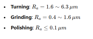
Surface roughness is typically represented by RaR_aRa, with the following calculation formula:

For common machining processes, roughness control ranges are as follows:
V. Tolerance Capabilities of Different Manufacturing Processes and Their Applications
When determining machining tolerances, consider not only part functionality and precision requirements but also evaluate the capabilities of the manufacturing process and equipment used. Each machining method offers different tolerance control ranges, so selecting the right process helps avoid unnecessary over-processing, reduces production costs, and improves efficiency. Below are some common machining processes, their typical tolerance ranges, and application scenarios:
| Machining Process | Typical Tolerance Range (mm) | Application Scenarios |
| Turning | ±0.05 ~ ±0.1 | Parts with moderate precision needs, such as shafts, sleeves, and threaded components |
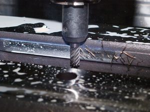
| Milling | ±0.05 ~ ±0.2 | Shape and planar machining, ideal for structural and framing parts |
| Grinding | ±0.005 ~ ±0.02 | High-precision parts, including bearing rings, guides, and precision bores |
| Electrical Discharge Machining (EDM) | ±0.002 ~ ±0.01 | Complex shapes and high-precision machining, such as molds, blades, and cavities |
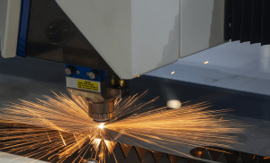
| Laser Cutting | ±0.1 ~ ±0.3 | Thin sheet cutting and complex contouring, suitable for batch processing |
| 3D Printing | ±0.1 ~ ±0.5 | Rapid prototyping and low-volume complex structures; precision varies with material and printing process |
VI. Cost-Benefit Analysis of Tolerance Selection
In practical production, tighter tolerances increase manufacturing complexity and costs. So, finding a balance between tolerance requirements and cost-effectiveness becomes essential. Use the following formula to calculate tolerance costs:
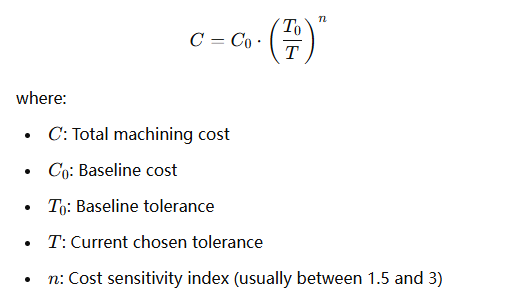
For example, when tightening a part’s tolerance from 0.1 mm to 0.05 mm, with a cost sensitivity index ( n = 2 ), costs will increase fourfold. This calculation highlights the importance of avoiding unnecessarily strict tolerances in practical applications.
VII. Common Tolerance Issues and Solutions
Issue 1: Misaligned assembly tolerances cause assembly difficulties.
Solution: Ensure that assembly components meet the required fit tolerances. Use standard fit tolerance grades (such as ISO’s H7/h6 for sliding fits or G7/f6 for slight interference fits) to set tolerance ranges for each mating dimension, ensuring proper clearance or interference. This approach helps maintain functionality and ease of assembly while reducing the risk of accumulated machining errors. Additionally, perform regular inspections on assembly dimensions to ensure they meet standards.
Issue 2: Excessive precision requirements drive up production costs.
Solution: Optimize tolerance allocation to control costs effectively. Begin with a functional analysis to identify critical and non-critical dimensions. Control tolerances strictly for dimensions essential to part performance and durability, but relax tolerances for non-critical dimensions to simplify manufacturing. Use tools like finite element analysis to aid in determining tolerance requirements for each section, optimizing design to reduce unnecessary precision demands and cut costs in machining, inspection, and equipment.
Issue 3: Material deformation affects tolerance accuracy.
Solution: Material stability plays a crucial role in achieving machining tolerances. For materials prone to deformation, consider using alloys with low thermal expansion or greater dimensional stability. Plan for processes like heat treatment or stress relief to reduce deformation caused by internal stress. For parts that may be affected by heat during machining, account for thermal expansion in tolerance design to ensure the final part meets size requirements.
Issue 4: Insufficient tolerance control capability in production equipment.
Solution: Confirm that the selected equipment can meet the target tolerance level. For high-precision work, use grinding machines or precision CNC machines; for moderate precision, consider lathes or conventional milling machines. Select suitable operations based on each machine’s specific accuracy level (such as positioning and repeatability) to ensure the finished part meets tolerance requirements. Perform regular calibration and maintenance on equipment to maintain consistent machining precision.
VIII. Conclusion: How to Scientifically Select Machining Tolerances in Practical Applications
When setting machining tolerances, combine scientific accuracy with practical considerations. First, clarify part function and operating conditions, identifying critical dimensions and tolerance requirements. Next, select appropriate processes and equipment to control tolerances effectively. Finally, assess the cost implications of each tolerance level, ensuring precision without unnecessary expense.
Through this guide, we hope you gain a clear understanding of machining tolerances to help you set optimal tolerance levels that achieve a balanced technical and economic outcome. For more insights, feel free to visit our website—our team is always ready to provide professional assistance.


